Diesel Database
Published: Sun, 03 Mar 2024 11:13:54Rust | Diesel
When I decided to start work on this project, I knew it would be important to carefully design the database. I did some research into software to draw an entity relationship diagram and a UML diagram to help me map out the project, and a friend suggested that I try plantuml. Plantuml is a java based application that builds diagrams from a very intuitive but powerful text based description syntax. It can create all different kinds of diagrams through the use of class definitions that load based on your text description.
Creating an ERD Diagram with Plantuml
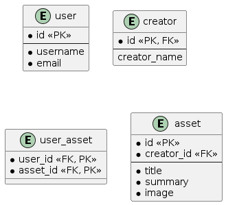
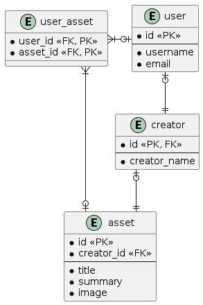
The web application I am designing is intended to host different types of assets for table-top role-playing games such as books, maps, music and so on. My strategy was to create a user table and use the primary key for that table in a one to one relationship with a creator table. The idea is that everyone is a user, but being a creator is optional. Instead of having the creator data fields nullable, I decided it made more sense to keep the information separate. Each asset is then stored in various asset tables that have a serial primary key and stores the id of the creator that owns them. In order to link ownership, I made a linking table that has a one to many relationship between the user table and the asset's table. This information can be easily created in a plantuml diagram like so:
' hide the spot
' hide circle

' avoid problems with angled crows feet
skinparam linetype ortho

entity user {
    * id <<PK>>
    --
    * username
    * email
}

entity creator {
    * id <<PK, FK>>
    --
    creator_name
}

entity user_asset {
    * user_id <<FK, PK>>
    * asset_id <<FK, PK>>
}

entity asset {
    * id <<PK>>
    * creator_id <<FK>>
    --
    * title
    * summary
    * image
}
This creates the four tables, but does nothing to link them up. The few lines at the top are used to set things up to correctly display an ERD diagram as it differs slightly from the default UML class implementation. The * creates a NOT NULL field and the -- is designed to indicate which of the fields are identifiers.

Plantuml uses a simple syntax in order to represent linkages. It is important to note that it is a drawing tool and will not prevent you from linking tables that might otherwise not be joinable.
user |o--|| creator
creator |o--|| asset
asset |o--|{ user_asset
user |o-left-|{ user_asset
Adding these lines below the table definitions will create linkages between the tables using a visually representative syntax that is very easy to remember. For example |o--|{ represents an optional one to mandatory many relationship and ||--|| would represent a mandatory one to one relationship. Detailed examples for all the possible combinations can be found in the ERD class documentation.

Creating a complimentary UML diagram
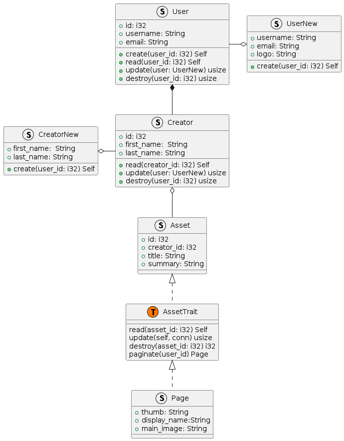
I didn't exactly make a UML diagram because Rust uses structs and traits instead of classes and interfaces, but I created a diagram that was inspired by UML. To do this I had to add some custom symbols to correctly display Rust data structures like traits and enums. I started by adding classes for each table and then created structs that would work well with Diesel. Diesel is an ORM that uses Rust structs along with macros to dynamically create SQL queries that are safer from SQL injection or other attacks. It also speeds up development by creating a schema of your database in Rust so that you will get compile time and language server errors if you try to do something incompatible with your schema.
struct User {
        + id: i32
        + username: String
        + email: String
        + create(user_id: i32) Self
        + read(user_id: i32) Self
        + update(user: UserNew) usize
        + destroy(user_id: i32) usize
}

struct UserNew {
        + username: String
        + email: String
        + logo: String
        + create(user_id: i32) Self
}

struct Creator {
        + id: i32
        + first_name:  String
        + last_name: String
        + read(creator_id: i32) Self
        + update(user: UserNew) usize
        + destroy(user_id: i32) usize
}

struct CreatorNew {
        + first_name:  String
        + last_name: String
        + create(user_id: i32) Self
}

class AssetTrait << (T,#FF7700) >>  {
        read(asset_id: i32) Self
        update(self, conn) usize
        destroy(asset_id: i32) i32
        paginate(user_id) Page
}

struct Page {
        + thumb: String
        + display_name:String
        + main_image: String
}

struct Asset {
        + id: i32
        + creator_id: i32
        + title: String
        + summary: String
}

UserNew o-left- User
CreatorNew o-right- Creator
User *-- Creator
Creator o-- Asset
Asset <|.. AssetTrait
AssetTrait <|.. Page
Similar to the ERD diagram, you create classes, but instead of using * you would use + to show public methods and variables. In order to display the Asset trait I used the << (T,#FF7700) >> syntax, which allows you to control the icon and the icon color for any arbitrary data structure.
